
2.2.1 Our First Image

|
|
2.2 Getting Started |
POV-Ray 3.6 for UNIX documentation 2.2.1 Our First Image |
2.2.2 Basic Shapes |
|
We will create the scene file for a simple picture. Since ray-tracers thrive on spheres, that is what we will render first.
First, we have to tell POV-Ray where our camera is and where it is looking. To do this, we use 3D coordinates. The usual coordinate system for POV-Ray has the positive y-axis pointing up, the positive x-axis pointing to the right, and the positive z-axis pointing into the screen as follows:
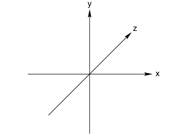
This kind of coordinate system is called a left-handed coordinate system. If we use our left hand's fingers we can easily see why it is called left-handed. We just point our thumb in the direction of the positive x-axis (to the right), the index finger in the direction of the positive y-axis (straight up) and the middle finger in the positive z-axis direction (forward). We can only do this with our left hand. If we had used our right hand we would not have been able to point the middle finger in the correct direction.
The left hand can also be used to determine rotation directions. To do this we must perform the famous "Computer Graphics Aerobics" exercise. We hold up our left hand and point our thumb in the positive direction of the axis of rotation. Our fingers will curl in the positive direction of rotation. Similarly if we point our thumb in the negative direction of the axis our fingers will curl in the negative direction of rotation.

In the above illustration, the left hand is curling around the x-axis. The thumb points in the positive x direction and the fingers curl over in the positive rotation direction.
If we want to use a right-handed system, as some CAD systems and modelers do, the right
vector in the camera specification needs to be changed. See the detailed description in "Handedness".
In a right-handed system we use our right hand for the "Aerobics".
There is some controversy over whether POV-Ray's method of doing a right-handed system is really proper. To avoid problems we stick with the left-handed system which is not in dispute.
Using our personal favorite text editor, we create a file called demo.pov. Some versions of POV-Ray
come with their own built-in text editor which may be easier to use. We then type in the following text. The input is
case sensitive, so we have to be sure to get capital and lowercase letters correct.
  #include "colors.inc"    // The include files contain
  #include "stones.inc"    // pre-defined scene elements
The first include statement reads in definitions for various useful colors. The second include statement reads in a collection of stone textures. POV-Ray comes with many standard include files. Others of interest are:
  #include "textures.inc"    // pre-defined scene elements
  #include "shapes.inc"
  #include "glass.inc"
  #include "metals.inc"
  #include "woods.inc"
They read pre-defined textures, shapes, glass, metal, and wood textures. It is a good idea to have a look through them to see a few of the many possible shapes and textures available.
We should only include files we really need in our scene. Some of the include files coming with POV-Ray are quite
large and we should better save the parsing time and memory if we do not need them. In the following examples we will
only use the colors.inc, and stones.inc include files.
We may have as many include files as needed in a scene file. Include files may themselves contain include files, but we are limited to declaring includes nested only ten levels deep.
Filenames specified in the include statements will be searched for in the current directory first. If it fails to
find your .Inc files in the current directory, POV-Ray searches any "library
paths" that you have specified. Library paths are options set by the +L command-line
switch or Library_Path option. See the chapter "Setting
POV-Ray Options" for more information on library paths.
Because it is more useful to keep include files in a separate directory, standard installations of POV-Ray place
these files in the c:\povray3\include directory (replace 'c:\povray3' with the actual directory that you installed
POV-Ray in). If you get an error message saying that POV-Ray cannot open "colors.inc" or other
include files, make sure that you specify the library path properly.
The camera statement describes where and how the camera sees the scene. It gives x-, y- and
z-coordinates to indicate the position of the camera and what part of the scene it is pointing at. We describe the
coordinates using a three-part vector. A vector is specified by putting three numeric values between a pair
of angle brackets and separating the values with commas. We add the following camera statement to the scene.
  camera {
    location <0, 2, -3>
    look_at  <0, 1,  2>
  }
Briefly, location <0,2,-3> places the camera up two units and back three units from the center
of the ray-tracing universe which is at <0,0,0>. By default +z is into the screen and -z is back out of the
screen.
Also look_at <0,1,2> rotates the camera to point at the coordinates <0,1,2>. A point 1
unit up from the origin and 2 units away from the origin. This makes it 5 units in front of and 1 unit lower than the
camera. The look_at point should be the center of attention of our image.
Now that the camera is set up to record the scene, let's place a yellow sphere into the scene. We add the following to our scene file:
  sphere {
    <0, 1, 2>, 2
    texture {
      pigment { color Yellow }
    }
  }
The first vector specifies the center of the sphere. In this example the x coordinate is zero so it is centered left and right. It is also at y=1 or one unit up from the origin. The z coordinate is 2 which is five units in front of the camera, which is at z=-3. After the center vector is a comma followed by the radius which in this case is two units. Since the radius is half the width of a sphere, the sphere is four units wide.
After we have defined the location and size of the sphere, we need to describe the appearance of the surface. The texture
statement specifies these parameters. Texture blocks describe the color, bumpiness and finish properties of an object.
In this example we will specify the color only. This is the minimum we must do. All other texture options except color
will use default values.
The color we define is the way we want an object to look if fully illuminated. If we were painting a picture of a
sphere we would use dark shades of a color to indicate the shadowed side and bright shades on the illuminated side.
However ray-tracing takes care of that for you. We only need to pick the basic color inherent in the object and
POV-Ray brightens or darkens it depending on the lighting in the scene. Because we are defining the basic color the
object actually has rather than how it looks the parameter is called pigment.
Many types of color patterns are available for use in a pigment statement. The keyword color specifies
that the whole object is to be one solid color rather than some pattern of colors. We can use one of the color
identifiers previously defined in the standard include file colors.inc.
If no standard color is available for our needs, we may define our own color by using the color
keyword followed by red, green, and blue keywords specifying the amount of
red, green and blue to be mixed. For example a nice shade of pink can be specified by:
color red 1.0 green 0.8 blue 0.8
Note: the international - rather than American - form "colour" is also acceptable and may be used anywhere that "color" may be used.
The values after each keyword should be in the range from 0.0 to 1.0. Any of the three components not specified will default to 0. A shortcut notation may also be used. The following produces the same shade of pink:
color rgb <1.0, 0.8, 0.8>
In many cases the color keyword is superfluous, so the shortest way to specify the pink color is:
rgb <1.0, 0.8, 0.8>
Colors are explained in more detail in section "Specifying Colors".
One more detail is needed for our scene. We need a light source. Until we create one, there is no light in this virtual world. Thus we add the line
light_source { <2, 4, -3> color White}
to the scene file to get our first complete POV-Ray scene file as shown below.
  #include "colors.inc"
  background { color Cyan }
  camera {
    location <0, 2, -3>
    look_at  <0, 1,  2>
  }
  sphere {
    <0, 1, 2>, 2
    texture {
      pigment { color Yellow }
    }
  }
  light_source { <2, 4, -3> color White}
The vector in the light_source statement specifies the location of the light as two units to our
right, four units above the origin and three units back from the origin. The light source is an invisible tiny point
that emits light. It has no physical shape, so no texture is needed.
That's it! We close the file and render a small picture of it using whatever methods you used for your particular platform. If you specified a preview display it will appear on your screen. If you specified an output file (the default is file output on), then POV-Ray also created a file.
Note: if you do not have high color or true color display hardware then the preview image may look poor but the full detail is written to the image file regardless of the type of display.
The scene we just traced is not quite state of the art but we will have to start with the basics before we soon get to much more fascinating features and scenes.
|
|
2.2 Getting Started | 2.2.1 Our First Image | 2.2.2 Basic Shapes |
|