
2.2.2 Basic Shapes

|
|
2.2.1 Our First Image |
POV-Ray 3.6 for UNIX documentation 2.2.2 Basic Shapes |
2.2.3 CSG Objects |
|
So far we have just used the sphere shape. There are many other types of shapes that can be rendered by POV-Ray. The following sections will describe how to use some of the more simple objects as a replacement for the sphere used above.
The box is one of the most common objects used. We try this example in place of the sphere:
  box {
    <-1, 0,   -1>,  // Near lower left corner
    < 1, 0.5,  3>   // Far upper right corner
    texture {
      T_Stone25     // Pre-defined from stones.inc
      scale 4       // Scale by the same amount in all
                    // directions
    }
    rotate y*20     // Equivalent to "rotate <0,20,0>"
  }
In the example we can see that a box is defined by specifying the 3D coordinates of its opposite corners. The first vector is generally the minimum x-, y- and z-coordinates and the 2nd vector should be the maximum x-, y- and z-values however any two opposite corners may be used. Box objects can only be defined parallel to the axes of the world coordinate system. We can later rotate them to any angle.
Note: we can perform simple math on values and vectors. In the rotate parameter we
multiplied the vector identifier y by 20. This is the same as <0,1,0>*20 or <0,20,0>.
Here is another example showing how to use a cone:
  cone {
    <0, 1, 0>, 0.3    // Center and radius of one end
    <1, 2, 3>, 1.0    // Center and radius of other end
    texture { T_Stone25 scale 4 }
  }
The cone shape is defined by the center and radius of each end. In this example one end is at location
<0,1,0> and has a radius of 0.3 while the other end is centered at <1,2,3> with a radius of 1. If we want
the cone to come to a sharp point we must use radius=0. The solid end caps are parallel to each other and
perpendicular to the cone axis. If we want an open cone with no end caps we have to add the keyword open
after the 2nd radius like this:
  cone {
    <0, 1, 0>, 0.3    // Center and radius of one end
    <1, 2, 3>, 1.0    // Center and radius of other end
    open              // Removes end caps
    texture { T_Stone25 scale 4 }
  }
We may also define a cylinder like this:
  cylinder {
    <0, 1, 0>,     // Center of one end
    <1, 2, 3>,     // Center of other end
    0.5            // Radius
    open           // Remove end caps
    texture { T_Stone25 scale 4 }
  }
Let's try out a computer graphics standard "The Checkered Floor". We add the following object to
the first version of the demo.pov file, the one including the sphere.
  plane { <0, 1, 0>, -1
    pigment {
      checker color Red, color Blue
    }
  }
The object defined here is an infinite plane. The vector <0,1,0> is the surface normal of the plane (i.e. if we were standing on the surface, the normal points straight up). The number afterward is the distance that the plane is displaced along the normal from the origin -- in this case, the floor is placed at y=-1 so that the sphere at y=1, radius=2, is resting on it.
Note: even though there is no texture statement there is an implied
texture here. We might find that continually typing statements that are nested like texture {pigment} can
get to be tiresome so POV-Ray let's us leave out the texture statement under many circumstances. In
general we only need the texture block surrounding a texture identifier (like the T_Stone25 example
above), or when creating layered textures (which are covered later).
This pigment uses the checker color pattern and specifies that the two colors red and blue should be used.
Because the vectors <1,0,0>, <0,1,0> and <0,0,1> are used frequently, POV-Ray has three built-in
vector identifiers x, y and z respectively that can be used as a shorthand.
Thus the plane could be defined as:
  plane { y, -1
    pigment { ... }
  }
Note: that we do not use angle brackets around vector identifiers.
Looking at the floor, we notice that the ball casts a shadow on the floor. Shadows are calculated very accurately by the ray-tracer, which creates precise, sharp shadows. In the real world, penumbral or "soft" shadows are often seen. Later we will learn how to use extended light sources to soften the shadows.
A torus can be thought of as a donut or an inner-tube. It is a shape that is vastly useful in many
kinds of CSG so POV-Ray has adopted this 4th order quartic polynomial as a primitive shape. The syntax for a torus is
so simple that it makes it a very easy shape to work with once we learn what the two float values mean. Instead of a
lecture on the subject, let's create one and do some experiments with it.
We create a file called tordemo.pov and edit it as follows:
  #include "colors.inc"
  camera {
    location <0, .1, -25>
    look_at 0
    angle 30
  }
  background { color Gray50 } // to make the torus easy to see
  light_source { <300, 300, -1000> White }
  torus {
    4, 1              // major and minor radius
    rotate -90*x      // so we can see it from the top
    pigment { Green }
  }
We trace the scene. Well, it is a donut alright. Let's try changing the major and minor radius values and see what happens. We change them as follows:
torus { 5, .25 // major and minor radius
That looks more like a hula-hoop! Let's try this:
torus { 3.5, 2.5 // major and minor radius
Whoa! A donut with a serious weight problem!
With such a simple syntax, there is not much else we can do to a torus besides change its texture... or is there? Let's see...
Tori are very useful objects in CSG. Let's try a little experiment. We make a difference of a torus and a box:
  difference {
    torus {
      4, 1
      rotate x*-90  // so we can see it from the top
    }
    box { <-5, -5, -1>, <5, 0, 1> }
    pigment { Green }
  }
Interesting... a half-torus. Now we add another one flipped the other way. Only, let's declare the original half-torus and the necessary transformations so we can use them again:
  #declare Half_Torus = difference {
    torus {
      4, 1
      rotate -90*x  // so we can see it from the top
    }
    box { <-5, -5, -1>, <5, 0, 1> }
    pigment { Green }
  }
  #declare Flip_It_Over = 180*x;
  #declare Torus_Translate = 8;  // twice the major radius
Now we create a union of two Half_Torus objects:
  union {
    object { Half_Torus }
    object { Half_Torus
      rotate Flip_It_Over
      translate Torus_Translate*x
    }
  }
This makes an S-shaped object, but we cannot see the whole thing from our present camera. Let's add a few more links, three in each direction, move the object along the +z-direction and rotate it about the +y-axis so we can see more of it. We also notice that there appears to be a small gap where the half Tori meet. This is due to the fact that we are viewing this scene from directly on the x-z-plane. We will change the camera's y-coordinate from 0 to 0.1 to eliminate this.
  union {
    object { Half_Torus }
    object { Half_Torus
      rotate Flip_It_Over
      translate x*Torus_Translate
    }
    object { Half_Torus
      translate x*Torus_Translate*2
    }
    object { Half_Torus
      rotate Flip_It_Over
      translate x*Torus_Translate*3
    }
    object { Half_Torus
      rotate Flip_It_Over
      translate -x*Torus_Translate
    }
    object { Half_Torus
      translate -x*Torus_Translate*2
    }
    object { Half_Torus
      rotate Flip_It_Over
      translate -x*Torus_Translate*3
    }
    object { Half_Torus
      translate -x*Torus_Translate*4
    }
    rotate y*45
    translate z*20
  }
Rendering this we see a cool, undulating, snake-like something-or-other. Neato. But we want to model something useful, something that we might see in real life. How about a chain?
Thinking about it for a moment, we realize that a single link of a chain can be easily modeled using two half tori
and two cylinders. We create a new file. We can use the same camera, background, light source and declared objects and
transformations as we used in tordemo.pov:
  #include "colors.inc"
  camera {
    location <0, .1, -25>
    look_at 0
    angle 30
  }
  background { color Gray50 }
  light_source{ <300, 300, -1000> White }
  #declare Half_Torus = difference {
    torus {
      4,1
      sturm
      rotate x*-90  // so we can see it from the top
    }
    box { <-5, -5, -1>, <5, 0, 1> }
    pigment { Green }
  }
  #declare Flip_It_Over = x*180;
  #declare Torus_Translate = 8;
Now, we make a complete torus of two half tori:
  union {
    object { Half_Torus }
    object { Half_Torus rotate Flip_It_Over }
  }
This may seem like a wasteful way to make a complete torus, but we are really going to move each half apart to make room for the cylinders. First, we add the declared cylinder before the union:
  #declare Chain_Segment = cylinder {
    <0, 4, 0>, <0, -4, 0>, 1
    pigment { Green }
  }
We then add two Chain_Segments to the union and translate them so that they line up with the minor
radius of the torus on each side:
  union {
    object { Half_Torus }
    object { Half_Torus rotate Flip_It_Over }
    object { Chain_Segment translate  x*Torus_Translate/2 }
    object { Chain_Segment translate -x*Torus_Translate/2 }
  }
Now we translate the two half tori +y and -y so that the clipped ends meet the ends of the cylinders. This distance
is equal to half of the previously declared Torus_Translate:
  union {
    object {
      Half_Torus
      translate y*Torus_Translate/2
    }
    object {
      Half_Torus
      rotate Flip_It_Over
      translate -y*Torus_Translate/2
    }
    object {
      Chain_Segment
      translate x*Torus_Translate/2
    }
    object {
      Chain_Segment
      translate -x*Torus_Translate/2
    }
  }
We render this and voila! A single link of a chain. But we are not done yet! Whoever heard of a green chain? We would rather use a nice metallic color instead. First, we remove any pigment blocks in the declared tori and cylinders. Then we add a declaration for a golden texture just before the union that creates the link. Finally, we add the texture to the union and declare it as a single link:
  #declare Half_Torus = difference {
    torus {
      4,1
      sturm
      rotate x*-90  // so we can see it from the top
    }
    box { <-5, -5, -1>, <5, 0, 1> }
  }

  #declare Chain_Segment = cylinder {
    <0, 4, 0>, <0, -4, 0>, 1
  }

  #declare Chain_Gold = texture {
    pigment { BrightGold }
    finish {
      ambient .1
      diffuse .4
      reflection .25
      specular 1
      metallic
    }
  }

  #declare Link = union {
    object {
      Half_Torus
      translate y*Torus_Translate/2
    }
    object {
      Half_Torus
      rotate Flip_It_Over
      translate -y*Torus_Translate/2
    }
    object {
      Chain_Segment
      translate x*Torus_Translate/2
    }
    object {
      Chain_Segment
      translate -x*Torus_Translate/2
    }    texture { Chain_Gold }
  }
Now we make a union of two links. The second one will have to be translated +y so that its inner wall just meets
the inner wall of the other link, just like the links of a chain. This distance turns out to be double the previously
declared Torus_Translate minus 2 (twice the minor radius). This can be described by the expression:
Torus_Translate*2-2*y
We declare this expression as follows:
#declare Link_Translate = Torus_Translate*2-2*y;
In the object block, we will use this declared value so that we can multiply it to create other links. Now, we
rotate the second link 90*y so that it is perpendicular to the first, just like links of a chain.
Finally, we scale the union by 1/4 so that we can see the whole thing:
  union {
    object { Link }
    object { Link translate y*Link_Translate rotate y*90 }
    scale .25
  }
We render this and we will see a very realistic pair of links. If we want to make an entire chain, we must declare the above union and then create another union of this declared object. We must be sure to remove the scaling from the declared object:
  #declare Link_Pair =
  union {
    object { Link }
    object { Link translate y*Link_Translate rotate y*90 }
  }
Now we declare our chain:
  #declare Chain = union {
    object { Link_Pair}
    object { Link_Pair translate  y*Link_Translate*2 }
    object { Link_Pair translate  y*Link_Translate*4 }
    object { Link_Pair translate  y*Link_Translate*6 }
    object { Link_Pair translate -y*Link_Translate*2 }
    object { Link_Pair translate -y*Link_Translate*4 }
    object { Link_Pair translate -y*Link_Translate*6 }
  }
And finally we create our chain with a couple of transformations to make it easier to see. These include scaling it down by a factor of 1/10, and rotating it so that we can clearly see each link:
object { Chain scale .1 rotate <0, 45, -45> }
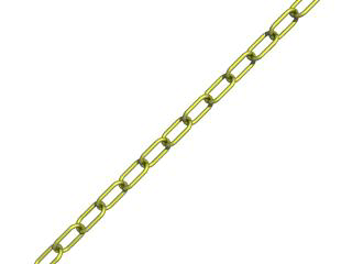
We render this and we should see a very realistic gold chain stretched diagonally across the screen.
|
|
2.2.1 Our First Image | 2.2.2 Basic Shapes | 2.2.3 CSG Objects |
|