
2.3.2 Polygon Based Shapes

|
|
2.3.1 Spline Based Shapes |
POV-Ray 3.6 for UNIX documentation 2.3.2 Polygon Based Shapes |
2.3.3 Other Shapes |
|
Mesh objects are very useful because they allow us to create objects containing hundreds or thousands of triangles. Compared to a simple union of triangles the mesh object stores the triangles more efficiently. Copies of mesh objects need only a little additional memory because the triangles are stored only once.
Almost every object can be approximated using triangles but we may need a lot of triangles to create more complex shapes. Thus we will only create a very simple mesh example. This example will show a very useful feature of the triangles meshes though: a different texture can be assigned to each triangle in the mesh.
Now let's begin. We will create a simple box with differently colored sides. We create an empty file called meshdemo.pov
and add the following lines. Note that a mesh is - not surprisingly - declared using the keyword mesh.
  camera {
    location <20, 20, -50>
    look_at <0, 5, 0>
  }
  light_source { <50, 50, -50> color rgb<1, 1, 1> }
  #declare Red = texture {
    pigment { color rgb<0.8, 0.2, 0.2> }
    finish { ambient 0.2 diffuse 0.5 }
  }
  #declare Green = texture {
    pigment { color rgb<0.2, 0.8, 0.2> }
    finish { ambient 0.2 diffuse 0.5 }
  }
  #declare Blue = texture {
    pigment { color rgb<0.2, 0.2, 0.8> }
    finish { ambient 0.2 diffuse 0.5 }
  }
We must declare all textures we want to use inside the mesh before the mesh is created. Textures cannot be specified inside the mesh due to the poor memory performance that would result.
Now we add the mesh object. Three sides of the box will use individual textures while the other will use the global mesh texture.
  mesh {
    /* top side */
    triangle {
      <-10, 10, -10>, <10, 10, -10>, <10, 10, 10>
      texture { Red }
    }
    triangle {
      <-10, 10, -10>, <-10, 10, 10>, <10, 10, 10>
      texture { Red }
    }
    /* bottom side */
    triangle { <-10, -10, -10>, <10, -10, -10>, <10, -10, 10> }
    triangle { <-10, -10, -10>, <-10, -10, 10>, <10, -10, 10> }
    /* left side */
    triangle { <-10, -10, -10>, <-10, -10, 10>, <-10, 10, 10> }
    triangle { <-10, -10, -10>, <-10, 10, -10>, <-10, 10, 10> }
    /* right side */
    triangle {
      <10, -10, -10>, <10, -10, 10>, <10, 10, 10>
      texture { Green }
    }
    triangle {
      <10, -10, -10>, <10, 10, -10>, <10, 10, 10>
      texture { Green }
    }
    /* front side */
    triangle {
      <-10, -10, -10>, <10, -10, -10>, <-10, 10, -10>
      texture { Blue }
    }
    triangle {
      <-10, 10, -10>, <10, 10, -10>, <10, -10, -10>
      texture { Blue }
    }
    /* back side */
    triangle { <-10, -10, 10>, <10, -10, 10>, <-10, 10, 10> }
    triangle { <-10, 10, 10>, <10, 10, 10>, <10, -10, 10> }
    texture {
      pigment { color rgb<0.9, 0.9, 0.9> }
      finish { ambient 0.2 diffuse 0.7 }
    }
  }
Tracing the scene at 320x240 we will see that the top, right and front side of the box have different textures.
Though this is not a very impressive example it shows what we can do with mesh objects. More complex examples, also
using smooth triangles, can be found under the scene directory as chesmsh.pov.
The mesh2 is a representation of a mesh, that is much more like POV-Ray's internal mesh representation
than the standard mesh. As a result, it parses faster and it file size is smaller.
Due to its nature, mesh2 is not really suitable for building meshes by hand, it is intended for use by
modelers and file format converters. An other option is building the meshes by macros. Yet, to understand the format,
we will do a small example by hand and go through all options.
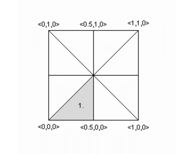
We will turn the mesh sketched above into a mesh2 object. The mesh is made of 8 triangles, each with 3
vertices, many of these vertices are shared among the triangles. This can later be used to optimize the mesh. First we
will set it up straight forward.
In mesh2 all the vertices are listed in a list named vertex_vectors{}. A second list, face_indices{},
tells us how to put together three vertices to create one triangle, by pointing to the index number of a vertex. All
lists in mesh2 are zero based, the number of the first vertex is 0. The very first item in a list is the
amount of vertices, normals or uv_vectors it contains. mesh2 has to be specified in the order VECTORS...,
LISTS..., INDICES....
Lets go through the mesh above, we do it counter clockwise. The total amount of vertices is 24 (8 triangle * 3 vertices).
mesh2 {
   vertex_vectors {
      24,
      ...
Now we can add the coordinates of the vertices of the first triangle:
mesh2 {
   vertex_vectors {
      24,
      <0,0,0>, <0.5,0,0>, <0.5,0.5,0>
      ..
Next step, is to tell the mesh how the triangle should be created; There will be a total of 8 face_indices (8 triangles). The first point in the first face, points to the first vertex_vector (0: <0,0,0>), the second to the second (1: <0.5,0,0>), etc...
mesh2 {
   vertex_vectors {
      24,
      <0,0,0>, <0.5,0,0>, <0.5,0.5,0>
      ...
   }
   face_indices {
      8,
      <0,1,2>
      ...
The complete mesh:
mesh2 {
   vertex_vectors {
      24,
      <0,0,0>, <0.5,0,0>, <0.5,0.5,0>, //1
      <0.5,0,0>, <1,0,0>, <0.5,0.5,0>, //2
      <1,0,0>, <1,0.5,0>, <0.5,0.5,0>, //3
      <1,0.5,0>, <1,1,0>, <0.5,0.5,0>, //4
      <1,1,0>, <0.5,1,0>, <0.5,0.5,0>, //5
      <0.5,1,0>, <0,1,0>, <0.5,0.5,0>, //6
      <0,1,0>, <0,0.5,0>, <0.5,0.5,0>, //7
      <0,0.5,0>, <0,0,0>, <0.5,0.5,0>  //8
   }
   face_indices {
      8,
      <0,1,2>,    <3,4,5>,       //1 2
      <6,7,8>,    <9,10,11>,     //3 4
      <12,13,14>, <15,16,17>,    //5 6
      <18,19,20>, <21,22,23>     //7 8
   }
   pigment {rgb 1}
}
As mentioned earlier, many vertices are shared by triangles. We can optimize the mesh by removing all duplicate vertices but one. In the example this reduces the amount from 24 to 9.
mesh2 {
   vertex_vectors {
      9,
      <0,0,0>, <0.5,0,0>, <0.5,0.5,0>,
      /*as 1*/ <1,0,0>,   /*as 2*/
      /*as 3*/ <1,0.5,0>, /*as 2*/
      /*as 4*/ <1,1,0>,   /*as 2*/
      /*as 5*/ <0.5,1,0>, /*as 2*/
      /*as 6*/ <0,1,0>,   /*as 2*/
      /*as 7*/ <0,0.5,0>, /*as 2*/
      /*as 8*/ /*as 0*/   /*as 2*/
   }
   ...
   ...
Next step is to rebuild the list of face_indices, as they now point to indices in the vertex_vector{}
list that do not exist anymore.
   ...
   ...
   face_indices {
      8,
      <0,1,2>, <1,3,2>,
      <3,4,2>, <4,5,2>,
      <5,6,2>, <6,7,2>,
      <7,8,2>, <8,0,2>
   }
   pigment {rgb 1}
}
In case we want a smooth mesh, the same steps we did also apply to the normals in a mesh. For each vertex there is
one normal vector listed in normal_vectors{}, duplicates can be removed. If the number of normals equals
the number of vertices then the normal_indices{} list is optional and the indexes from the face_indices{}
list are used instead.
mesh2 {
   vertex_vectors {
      9,
      <0,0,0>, <0.5,0,0>, <0.5,0.5,0>,
      <1,0,0>, <1,0.5,0>, <1,1,0>,
      <0.5,1,0>, <0,1,0>, <0,0.5,0>
   }
   normal_vectors {
      9,
     <-1,-1,0>,<0,-1,0>, <0,0,1>,
      /*as 1*/ <1,-1,0>, /*as 2*/
      /*as 3*/ <1,0,0>,  /*as 2*/
      /*as 4*/ <1,1,0>,  /*as 2*/
      /*as 5*/ <0,1,0>,  /*as 2*/
      /*as 6*/ <-1,1,0>, /*as 2*/
      /*as 7*/ <-1,0,0>, /*as 2*/
      /*as 8*/ /*as 0*/  /*as 2*/
   }
   face_indices {
      8,
      <0,1,2>, <1,3,2>,
      <3,4,2>, <4,5,2>,
      <5,6,2>, <6,7,2>,
      <7,8,2>, <8,0,2>
   }
   pigment {rgb 1}
}
When a mesh has a mix of smooth and flat triangles a list of normal_indices{} has to be added, where
each entry points to what vertices a normal should be applied. In the example below only the first four normals are
actually used.
mesh2 {
   vertex_vectors {
      9,
      <0,0,0>, <0.5,0,0>, <0.5,0.5,0>,
      <1,0,0>, <1,0.5,0>, <1,1,0>,
      <0.5,1,0>, <0,1,0>,   <0,0.5,0>
   }
   normal_vectors {
      9,
      <-1,-1,0>, <0,-1,0>, <0,0,1>,
      <1,-1,0>, <1,0,0>, <1,1,0>,
      <0,1,0>, <-1,1,0>, <-1,0,0>
   }
   face_indices {
      8,
      <0,1,2>, <1,3,2>,
      <3,4,2>, <4,5,2>,
      <5,6,2>, <6,7,2>,
      <7,8,2>, <8,0,2>
   }
   normal_indices {
      4,
      <0,1,2>, <1,3,2>,
      <3,4,2>, <4,5,2>
   }
   pigment {rgb 1}
}
uv_mapping is a method of 'sticking' 2D textures on an object in such a way that it follows the form of the object. For uv_mapping on triangles imagine it as follows; First you cut out a triangular section of a texture form the xy-plane. Then stretch, shrink and deform the piece of texture to fit to the triangle and stick it on.
Now, in mesh2 we first build a list of 2D-vectors that are the coordinates of the triangular sections
in the xy-plane. This is the uv_vectors{} list. In the example we map the texture from the rectangular
area <-0.5,-0.5>, <0.5,0.5> to the triangles in the mesh. Again we can omit all duplicate
coordinates
mesh2 {
   vertex_vectors {
      9,
      <0,0,0>, <0.5,0,0>, <0.5,0.5,0>,
      <1,0,0>, <1,0.5,0>, <1,1,0>,
      <0.5,1,0>, <0,1,0>,   <0,0.5,0>
   }
   uv_vectors {
      9
     <-0.5,-0.5>,<0,-0.5>,  <0,0>,
      /*as 1*/   <0.5,-0.5>,/*as 2*/
      /*as 3*/   <0.5,0>,   /*as 2*/
      /*as 4*/   <0.5,0.5>, /*as 2*/
      /*as 5*/   <0,0.5>,   /*as 2*/
      /*as 6*/   <-0.5,0.5>,/*as 2*/
      /*as 7*/   <-0.5,0>,  /*as 2*/
      /*as 8*/   /*as 0*/   /*as 2*/
   }
   face_indices {
      8,
      <0,1,2>, <1,3,2>,
      <3,4,2>, <4,5,2>,
      <5,6,2>, <6,7,2>,
      <7,8,2>, <8,0,2>
   }
   uv_mapping
   pigment {wood scale 0.2}
}
Just as with the normal_vectors, if the number of uv_vectors equals the number of
vertices then the uv_indices{} list is optional and the indices from the face_indices{} list
are used instead.
In contrary to the normal_indices list, if the uv_indices list is used, the amount of
indices should be equal to the amount of face_indices. In the example below only 'one texture section' is
specified and used on all triangles, using the uv_indices.
mesh2 {
   vertex_vectors {
      9,
      <0,0,0>, <0.5,0,0>, <0.5,0.5,0>,
      <1,0,0>, <1,0.5,0>, <1,1,0>,
      <0.5,1,0>, <0,1,0>,   <0,0.5,0>
   }
   uv_vectors {
      3
      <0,0>, <0.5,0>, <0.5,0.5>
   }
   face_indices {
      8,
      <0,1,2>, <1,3,2>,
      <3,4,2>, <4,5,2>,
      <5,6,2>, <6,7,2>,
      <7,8,2>, <8,0,2>
   }
   uv_indices {
      8,
      <0,1,2>, <0,1,2>,
      <0,1,2>, <0,1,2>,
      <0,1,2>, <0,1,2>,
      <0,1,2>, <0,1,2>
   }
   uv_mapping
   pigment {gradient x scale 0.2}
}
By using the texture_list it is possible to specify a texture per triangle or even per vertex in the
mesh. In the latter case the three textures per triangle will be interpolated. To let POV-Ray know what texture to
apply to a triangle, the index of a texture is added to the face_indices list, after the face index it
belongs to.
mesh2 {
   vertex_vectors {
      9,
      <0,0,0>, <0.5,0,0>, <0.5,0.5,0>,
      <1,0,0>, <1,0.5,0>, <1,1,0>
      <0.5,1,0>, <0,1,0>, <0,0.5,0>
   }
   texture_list {
      2,
      texture{pigment{rgb<0,0,1>}}
      texture{pigment{rgb<1,0,0>}}
   }
   face_indices {
      8,
      <0,1,2>,0,  <1,3,2>,1,
      <3,4,2>,0,  <4,5,2>,1,
      <5,6,2>,0,  <6,7,2>,1,
      <7,8,2>,0,  <8,0,2>,1
   }
}
To specify a texture per vertex, three texture_list indices are added after the face_indices
mesh2 {
   vertex_vectors {
      9,
      <0,0,0>, <0.5,0,0>, <0.5,0.5,0>,
      <1,0,0>, <1,0.5,0>, <1,1,0>
      <0.5,1,0>, <0,1,0>, <0,0.5,0>
   }
   texture_list {
      3,
      texture{pigment{rgb <0,0,1>}}
      texture{pigment{rgb 1}}
      texture{pigment{rgb <1,0,0>}}
   }
   face_indices {
      8,
      <0,1,2>,0,1,2,  <1,3,2>,1,0,2,
      <3,4,2>,0,1,2,  <4,5,2>,1,0,2,
      <5,6,2>,0,1,2,  <6,7,2>,1,0,2,
      <7,8,2>,0,1,2,  <8,0,2>,1,0,2
   }
}
Assigning a texture based on the texture_list and texture interpolation is done on a per triangle
base. So it is possible to mix triangles with just one texture and triangles with three textures in a mesh. It is even
possible to mix in triangles without any texture indices, these will get their texture from a general texture
statement in the mesh2. uv_mapping is supported for texturing using a texture_list.
The polygon object can be used to create any planar, n-sided
shapes like squares, rectangles, pentagons, hexagons, octagons, etc.
A polygon is defined by a number of points that describe its shape. Since polygons have to be closed the first point has to be repeated at the end of the point sequence.
In the following example we will create the word "POV" using just one polygon statement.
We start with thinking about the points we need to describe the desired shape. We want the letters to lie in the x-y-plane with the letter O being at the center. The letters extend from y=0 to y=1. Thus we get the following points for each letter (the z coordinate is automatically set to zero).
Letter P (outer polygon):
    <-0.8, 0.0>, <-0.8, 1.0>,
    <-0.3, 1.0>, <-0.3, 0.5>,
    <-0.7, 0.5>, <-0.7, 0.0>
Letter P (inner polygon):
    <-0.7, 0.6>, <-0.7, 0.9>,
    <-0.4, 0.9>, <-0.4, 0.6>
Letter O (outer polygon):
    <-0.25, 0.0>, <-0.25, 1.0>,
    < 0.25, 1.0>, < 0.25, 0.0>
Letter O (inner polygon):
    <-0.15, 0.1>, <-0.15, 0.9>,
    < 0.15, 0.9>, < 0.15, 0.1>
Letter V:
    <0.45, 0.0>, <0.30, 1.0>,
    <0.40, 1.0>, <0.55, 0.1>,
    <0.70, 1.0>, <0.80, 1.0>,
    <0.65, 0.0>
Both letters P and O have a hole while the letter V consists of only one polygon. We will start with the letter V because it is easier to define than the other two letters.
We create a new file called polygdem.pov and add the following text.
  camera {
    orthographic
    location <0, 0, -10>
    right 1.3 * 4/3 * x
    up 1.3 * y
    look_at <0, 0.5, 0>
  }
  light_source { <25, 25, -100> color rgb 1 }
  polygon {
    8,
    <0.45, 0.0>, <0.30, 1.0>, // Letter "V"
    <0.40, 1.0>, <0.55, 0.1>,
    <0.70, 1.0>, <0.80, 1.0>,
    <0.65, 0.0>,
    <0.45, 0.0>
    pigment { color rgb <1, 0, 0> }
  }
As noted above the polygon has to be closed by appending the first point to the point sequence. A closed polygon is always defined by a sequence of points that ends when a point is the same as the first point.
After we have created the letter V we will continue with the letter P. Since it has a hole we have to find a way of cutting this hole into the basic shape. This is quite easy. We just define the outer shape of the letter P, which is a closed polygon, and add the sequence of points that describes the hole, which is also a closed polygon. That is all we have to do. There will be a hole where both polygons overlap.
In general we will get holes whenever an even number of sub-polygons inside a single polygon statement overlap. A sub-polygon is defined by a closed sequence of points.
The letter P consists of two sub-polygons, one for the outer shape and one for the hole. Since the hole polygon overlaps the outer shape polygon we will get a hole.
After we have understood how multiple sub-polygons in a single polygon statement work, it is quite easy to add the missing O letter.
Finally, we get the complete word POV.
  polygon {
    30,
    <-0.8, 0.0>, <-0.8, 1.0>,    // Letter "P"
    <-0.3, 1.0>, <-0.3, 0.5>,    // outer shape
    <-0.7, 0.5>, <-0.7, 0.0>,
    <-0.8, 0.0>,
    <-0.7, 0.6>, <-0.7, 0.9>,    // hole
    <-0.4, 0.9>, <-0.4, 0.6>,
    <-0.7, 0.6>
    <-0.25, 0.0>, <-0.25, 1.0>,  // Letter "O"
    < 0.25, 1.0>, < 0.25, 0.0>,  // outer shape
    <-0.25, 0.0>,
    <-0.15, 0.1>, <-0.15, 0.9>,  // hole
    < 0.15, 0.9>, < 0.15, 0.1>,
    <-0.15, 0.1>,
    <0.45, 0.0>, <0.30, 1.0>,    // Letter "V"
    <0.40, 1.0>, <0.55, 0.1>,
    <0.70, 1.0>, <0.80, 1.0>,
    <0.65, 0.0>,
    <0.45, 0.0>
    pigment { color rgb <1, 0, 0> }
  }

|
|
2.3.1 Spline Based Shapes | 2.3.2 Polygon Based Shapes | 2.3.3 Other Shapes |
|