
3.3.1 Camera

|
|
3.3 Scene Settings |
POV-Ray 3.6 for UNIX documentation 3.3.1 Camera |
3.3.2 Atmospheric Effects |
|
The camera definition describes the position, projection type and properties of the camera viewing the scene. Its syntax is:
CAMERA:
    camera{ [CAMERA_ITEMS...] }
CAMERA_ITEM:
    CAMERA_TYPE | CAMERA_VECTOR | CAMERA_MODIFIER |
    CAMERA_IDENTIFIER
CAMERA_TYPE:
    perspective | orthographic | fisheye | ultra_wide_angle |
    omnimax | panoramic | cylinder CylinderType | spherical
CAMERA_VECTOR:
    location <Location> | right <Right> | up <Up> |
    direction <Direction> | sky <Sky>
CAMERA_MODIFIER:
    angle HORIZONTAL [VERTICAL] | look_at <Look_At> |
    blur_samples Num_of_Samples | aperture Size |
    focal_point <Point> | confidence Blur_Confidence |
    variance Blur_Variance | NORMAL | TRANSFORMATION
DEFAULT CAMERA:
  camera {
    perspective
    location <0,0,0>
    direction <0,0,1>
    right 1.33*x
    up y
    sky <0,1,0>
  }

CAMERA TYPE: perspective
angle      : ~67.380 ( direction_length=0.5*
                       right_length/tan(angle/2) )
confidence : 0.9 (90%)
direction  : <0,0,1>
focal_point: <0,0,0>
location   : <0,0,0>
look_at    : z
right      : 1.33*x
sky        : <0,1,0>
up         : y
variance   : 1/128
Depending on the projection type zero or more of the parameters are required:
The POV-Ray camera has ten different models, each of which uses a different projection method to project the scene
onto your screen. Regardless of the projection type all cameras use the location, right, up,
direction, and keywords to determine the location and orientation of the camera. The type keywords and
these four vectors fully define the camera. All other camera modifiers adjust how the camera does its job. The meaning
of these vectors and other modifiers differ with the projection type used. A more detailed explanation of the camera
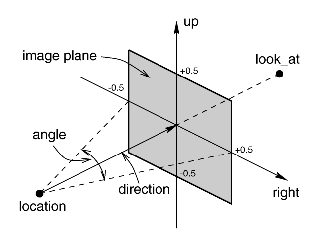
types follows later. In the sub-sections which follows, we explain how to place and orient the camera by the use of
these four vectors and the sky and look_at modifiers. You may wish to refer to the
illustration of the perspective camera below as you read about these vectors.
Under many circumstances just two vectors in the camera statement are all you need to position the camera: location
and look_at vectors. For example:
 camera {
  location <3,5,-10>
  look_at <0,2,1>
 }
The location is simply the x, y, z coordinates of the camera. The camera can be located anywhere in the ray-tracing
universe. The default location is <0,0,0>. The look_at vector tells POV-Ray to pan and
tilt the camera until it is looking at the specified x, y, z coordinates. By default the camera looks at a point one
unit in the z-direction from the location.
The look_at modifier should almost always be the last item in the camera statement. If other camera
items are placed after the look_at vector then the camera may not continue to look at the specified
point.
Normally POV-Ray pans left or right by rotating about the y-axis until it lines up with the look_at
point and then tilts straight up or down until the point is met exactly. However you may want to slant the camera
sideways like an airplane making a banked turn. You may change the tilt of the camera using the sky
vector. For example:
 camera {
  location <3,5,-10>
  sky   <1,1,0>
  look_at <0,2,1>
 }
This tells POV-Ray to roll the camera until the top of the camera is in line with the sky vector. Imagine that the
sky vector is an antenna pointing out of the top of the camera. Then it uses the sky vector as the axis
of rotation left or right and then to tilt up or down in line with the sky until pointing at the look_at
point. In effect you are telling POV-Ray to assume that the sky isn't straight up.
The sky vector does nothing on its own. It only modifies the way the look_at vector turns
the camera. The default value is sky<0,1,0>.
The angle keyword followed by a float expression specifies the (horizontal) viewing angle in degrees
of the camera used. Even though it is possible to use the direction vector to determine the viewing angle
for the perspective camera it is much easier to use the angle keyword.
When you specify the angle, POV-Ray adjusts the length of the direction vector
accordingly. The formula used is direction_length = 0.5 * right_length / tan(angle / 2) where
right_length is the length of the right vector. You should therefore specify the direction
and right vectors before the angle keyword. The right vector is explained in
the next section.
There is no limitation to the viewing angle except for the perspective projection. If you choose viewing angles larger than 360 degrees you will see repeated images of the scene (the way the repetition takes place depends on the camera). This might be useful for special effects.
The spherical camera has the option to also specify a vertical angle. If not specified it defaults to
the horizontal angle/2
For example if you render an image with a 2:1 aspect ratio and map it to a sphere using spherical mapping, it will recreate the scene. Another use is to map it onto an object and if you specify transformations for the object before the texture, say in an animation, it will look like reflections of the environment (sometimes called environment mapping).
You will probably not need to explicitly specify or change the camera direction vector but it is
described here in case you do. It tells POV-Ray the initial direction to point the camera before moving it with the look_at
or rotate vectors (the default value is direction<0,0,1>). It may also be used to
control the (horizontal) field of view with some types of projection. The length of the vector determines the distance
of the viewing plane from the camera's location. A shorter direction vector gives a wider view while a
longer vector zooms in for close-ups. In early versions of POV-Ray, this was the only way to adjust field of view.
However zooming should now be done using the easier to use angle keyword.
If you are using the ultra_wide_angle, panoramic, or cylindrical projection
you should use a unit length direction vector to avoid strange results. The length of the
direction vector does not matter when using the orthographic, fisheye, or omnimax
projection types.
The primary purpose of the up and right vectors is to tell POV-Ray the relative height
and width of the view screen. The default values are:
 right 4/3*x
 up y
In the default perspective camera, these two vectors also define the initial plane of the view screen
before moving it with the look_at or rotate vectors. The length of the right
vector (together with the direction vector) may also be used to control the (horizontal) field of view
with some types of projection. The look_at modifier changes both the up and right
vectors. The angle calculation depends on the right vector.
Most camera types treat the up and right vectors the same as the perspective
type. However several make special use of them. In the orthographic projection: The lengths of the
up and right vectors set the size of the viewing window regardless of the direction
vector length, which is not used by the orthographic camera.
When using cylindrical projection: types 1 and 3, the axis of the cylinder lies along the up
vector and the width is determined by the length of right vector or it may be overridden with the angle
vector. In type 3 the up vector determines how many units high the image is. For example if you have up
4*y on a camera at the origin. Only points from y=2 to y=-2 are visible. All viewing rays are perpendicular to
the y-axis. For type 2 and 4, the cylinder lies along the right vector. Viewing rays for type 4 are
perpendicular to the right vector.
Note: that the up, right, and direction
vectors should always remain perpendicular to each other or the image will be distorted. If this is not the case a
warning message will be printed. The vista buffer will not work for non-perpendicular camera vectors.
Together the up and right vectors define the aspect ratio (height to width
ratio) of the resulting image. The default values up<0,1,0> and right<1.33,0,0>
result in an aspect ratio of 4 to 3. This is the aspect ratio of a typical computer monitor. If you wanted a tall
skinny image or a short wide panoramic image or a perfectly square image you should adjust the up and right
vectors to the appropriate proportions.
Most computer video modes and graphics printers use perfectly square pixels. For example Macintosh displays and IBM
SVGA modes 640x480, 800x600 and 1024x768 all use square pixels. When your intended viewing method uses square pixels
then the width and height you set with the Width and Height options or +W or +H
switches should also have the same ratio as the up and right vectors.
Note: 640/480 = 4/3 so the ratio is proper for this square pixel mode.
Not all display modes use square pixels however. For example IBM VGA mode 320x200 and Amiga 320x400 modes do not
use square pixels. These two modes still produce a 4/3 aspect ratio image. Therefore images intended to be viewed on
such hardware should still use 4/3 ratio on their up and right vectors but the pixel
settings will not be 4/3.
For example:
 camera {
  location <3,5,-10>
  up    <0,1,0>
  right  <1,0,0>
  look_at <0,2,1>
 }
This specifies a perfectly square image. On a square pixel display like SVGA you would use pixel settings such as +W480
+H480 or +W600 +H600. However on the non-square pixel Amiga 320x400 mode you would want to use
values of +W240 +H400 to render a square image.
The bottom line issue is this: the up and right vectors should specify the artist's
intended aspect ratio for the image and the pixel settings should be adjusted to that same ratio for square pixels and
to an adjusted pixel resolution for non-square pixels. The up and right vectors should
not be adjusted based on non-square pixels.
The right vector also describes the direction to the right of the camera. It tells POV-Ray where the
right side of your screen is. The sign of the right vector can be used to determine the handedness of the
coordinate system in use. The default value is: right<1.33,0,0>. This means that the +x-direction
is to the right. It is called a left-handed system because you can use your left hand to keep track of the
axes. Hold out your left hand with your palm facing to your right. Stick your thumb up. Point straight ahead with your
index finger. Point your other fingers to the right. Your bent fingers are pointing to the +x-direction. Your thumb
now points into +y-direction. Your index finger points into the +z-direction.
To use a right-handed coordinate system, as is popular in some CAD programs and other ray-tracers, make the same
shape using your right hand. Your thumb still points up in the +y-direction and your index finger still points forward
in the +z-direction but your other fingers now say the +x-direction is to the left. That means that the right side of
your screen is now in the -x-direction. To tell POV-Ray to act like this you can use a negative x value in the
right vector such as: right<-1.33,0,0>. Since having x values increasing to the left does
not make much sense on a 2D screen you now rotate the whole thing 180 degrees around by using a positive z value in
your camera's location. You end up with something like this.
 camera {
  location <0,0,10>
  up    <0,1,0>
  right  <-1.33,0,0>
  look_at <0,0,0>
 }
Now when you do your ray-tracer's aerobics, as explained in the section "Understanding POV-Ray's Coordinate System", you use your right hand to determine the direction of rotations.
In a two dimensional grid, x is always to the right and y is up. The two versions of handedness arise from the question of whether z points into the screen or out of it and which axis in your computer model relates to up in the real world.
Architectural CAD systems, like AutoCAD, tend to use the God's Eye orientation that the z-axis is the elevation and is the model's up direction. This approach makes sense if you are an architect looking at a building blueprint on a computer screen. z means up, and it increases towards you, with x and y still across and up the screen. This is the basic right handed system.
Stand alone rendering systems, like POV-Ray, tend to consider you as a participant. You are looking at the screen as if you were a photographer standing in the scene. The up direction in the model is now y, the same as up in the real world and x is still to the right, so z must be depth, which increases away from you into the screen. This is the basic left handed system.
The various transformations such as translate and rotate modifiers can re-position the
camera once you have defined it. For example:
 camera {
  location < 0, 0, 0>
  direction < 0, 0, 1>
  up    < 0, 1, 0>
  right   < 1, 0, 0>
  rotate  <30, 60, 30>
  translate < 5, 3, 4>
 }
In this example, the camera is created, then rotated by 30 degrees about the x-axis, 60 degrees about the y-axis and 30 degrees about the z-axis, then translated to another point in space.
The following list explains the different projection types that can be used with the camera. The most common types
are the perspective and orthographic projections. The CAMERA_TYPE should be the first item in a camera
statement. If none is specified, the perspective camera is the default.
You should note that the vista buffer can only be used with the perspective and orthographic camera.
The perspective keyword specifies the default perspective camera which simulates the classic pinhole
camera. The (horizontal) viewing angle is either determined by the ratio between the length of the direction
vector and the length of the right vector or by the optional keyword angle, which is the
preferred way. The viewing angle has to be larger than 0 degrees and smaller than 180 degrees. See the figure in
"Placing the Camera" for the geometry of the perspective camera.
The orthographic camera offers two modes of operation:
The pure orthographic projection. This projection uses parallel camera rays to create an image of the
scene. The area of view is determined by the lengths of the right and up vectors. One of
these has to be specified, they are not taken from the default camera. If omitted the second method of the camera is
used.
If, in a perspective camera, you replace the perspective keyword by orthographic and
leave all other parameters the same, you will get an orthographic view with the same image area, i.e. the size of the
image is the same. The same can be achieved by adding the angle keyword to an orthographic camera. A
value for the angle is optional. So this second mode is active if no up and right are within the camera statement, or
when the angle keyword is within the camera statement.
You should be aware though that the visible parts of the scene change when switching from perspective to orthographic view. As long as all objects of interest are near the look_at point they will be still visible if the orthographic camera is used. Objects farther away may get out of view while nearer objects will stay in view.
If objects are too close to the camera location they may disappear. Too close here means, behind the orthographic
camera projection plane (the plane that goes through the look_at point).
This is a spherical projection. The viewing angle is specified by the angle keyword. An angle of 180
degrees creates the "standard" fisheye while an angle of 360 degrees creates a super-fisheye
("I-see-everything-view"). If you use this projection you should get a circular image. If this is not the
case, i.e. you get an elliptical image, you should read "Aspect Ratio".
This projection is somewhat similar to the fisheye but it projects the image onto a rectangle instead of a circle.
The viewing angle can be specified using the angle keyword.
The omnimax projection is a 180 degrees fisheye that has a reduced viewing angle in the vertical direction. In
reality this projection is used to make movies that can be viewed in the dome-like Omnimax theaters. The image will
look somewhat elliptical. The angle keyword is not used with this projection.
This projection is called "cylindrical equirectangular projection". It overcomes the degeneration problem
of the perspective projection if the viewing angle approaches 180 degrees. It uses a type of cylindrical projection to
be able to use viewing angles larger than 180 degrees with a tolerable lateral-stretching distortion. The angle
keyword is used to determine the viewing angle.
Using this projection the scene is projected onto a cylinder. There are four different types of cylindrical
projections depending on the orientation of the cylinder and the position of the viewpoint. A float value in the range
1 to 4 must follow the cylinder keyword. The viewing angle and the length of the up or right
vector determine the dimensions of the camera and the visible image. The camera to use is specified by a number. The
types are:
Using this projection the scene is projected onto a sphere.
Syntax:
  camera {
    spherical
    [angle HORIZONTAL [VERTICAL]]
    [CAMERA_ITEMS...]
  }
The first value after angle sets the horizontal viewing angle of the camera. With the optional second
value, the vertical viewing angle is set: both in degrees. If the vertical angle is not specified, it defaults to half
the horizontal angle.
The spherical projection is similar to the fisheye projection, in that the scene is projected on a sphere. But unlike the fisheye camera, it uses rectangular coordinates instead of polar coordinates; in this it works the same way as spherical mapping (map_type 1).
This has a number of uses. Firstly, it allows an image rendered with the spherical camera to be mapped on a sphere without distortion (with the fisheye camera, you first have to convert the image from polar to rectangular coordinates in some image editor). Also, it allows effects such as "environment mapping", often used for simulating reflections in scanline renderers.
POV-Ray can simulate focal depth-of-field by shooting a number of sample rays from jittered points within each pixel and averaging the results.
To turn on focal blur, you must specify the aperture keyword followed by a float value which
determines the depth of the sharpness zone. Large apertures give a lot of blurring, while narrow apertures will give a
wide zone of sharpness.
Note: while this behaves as a real camera does, the values for aperture are purely arbitrary and are not related to f-stops.
You must also specify the blur_samples keyword followed by an integer value specifying the maximum
number of rays to use for each pixel. More rays give a smoother appearance but is slower. By default no focal blur is
used, i. e. the default aperture is 0 and the default number of samples is 0.
The center of the zone of sharpness is specified by the focal_point vector. The zone of
sharpness is a plane through the focal_point and is parallel to the camera. Objects close to this
plane of focus are in focus and those farther from that plane are more blurred. The default value is
focal_point<0,0,0>.
Although blur_samples specifies the maximum number of samples, there is an adaptive mechanism that
stops shooting rays when a certain degree of confidence has been reached. At that point, shooting more rays would not
result in a significant change.
The confidence and variance keywords are followed by float values to control the
adaptive function. The confidence value is used to determine when the samples seem to be close enough
to the correct color. The variance value specifies an acceptable tolerance on the variance of the
samples taken so far. In other words, the process of shooting sample rays is terminated when the estimated color value
is very likely (as controlled by the confidence probability) near the real color value.
Since the confidence is a probability its values can range from 0 to <1 (the default is 0.9, i. e.
90%). The value for the variance should be in the range of the smallest displayable color difference
(the default is 1/128). If 1 is used POV-Ray will issue a warning and then use the default instead.
Rendering with the default settings can result in quite grainy images. This can be improved by using a lower variance.
A value of 1/10000 gives a fairly good result (with default confidence and blur_samples set to something like 100)
without being unacceptably slow.
Larger confidence values will lead to more samples, slower traces and better images. The same holds
for smaller variance thresholds.
The optional normal may be used to assign a normal pattern to the camera. For
example:
 camera{
   location Here
   look_at There
   normal { bumps 0.5 }
 }
All camera rays will be perturbed using this pattern. The image will be distorted as though you were looking
through bumpy glass or seeing a reflection off of a bumpy surface. This lets you create special effects. See the
animated scene camera2.pov for an example. See "Normal" for information on normal patterns.
Camera identifiers may be declared to make scene files more readable and to parameterize scenes so that changing a single declaration changes many values. You may declare several camera identifiers if you wish. This makes it easy to quickly change cameras. An identifier is declared as follows.
CAMERA_DECLARATION:
    #declare IDENTIFIER = CAMERA |
    #local IDENTIFIER = CAMERA
Where IDENTIFIER is the name of the identifier up to 40 characters long and CAMERA is any valid camera statement. See "#declare vs. #local" for information on identifier scope. Here is an example...
 #declare Long_Lens = camera {
    location -z*100
    look_at <0,0,0>
    angle 3
 }

 #declare Short_Lens = camera {
    location -z*50
    look_at <0,0,0>
    angle 15
 }

 camera {
    Long_Lens  // edit this line to change lenses
    translate <33,2,0>
 }
Note: only camera transformations can be added to an already declared camera. Camera behaviour changing keywords are not allowed, as they are needed in an earlier stage for resolving the keyword order dependencies.
|
|
3.3 Scene Settings | 3.3.1 Camera | 3.3.2 Atmospheric Effects |
|